SEED is an Equipment supplier that also provides consultation services and System Integration (SI) capability.
Thereby SEED can provide one-stop solution from design to installation of equipment.
International team of engineers with experience in dealing with multinational customers and in-depth knowledge of international best practices.
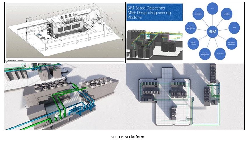
BIM Expert in Design and Project management. SEED is the leading pioneer in BIM platform design and management for Data center critical infrastructure design and build.
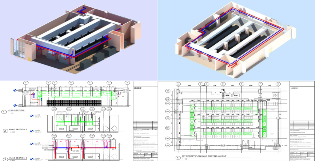
Design 3D Illustration & BIM Platform
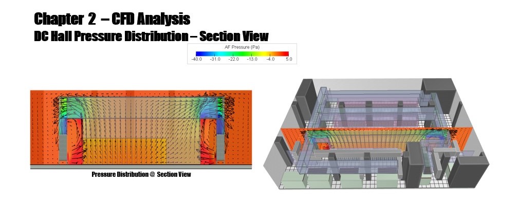
Design CFD Study
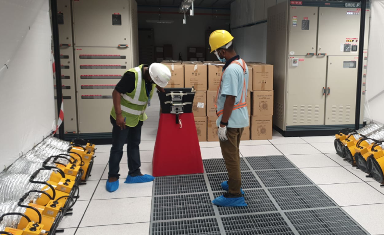
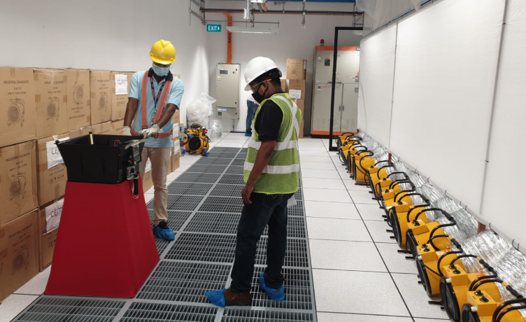
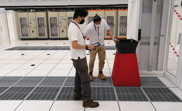
Real Case Study
IT Load per Rack(kW)
Server Quantity
Subtotal IT Load (kW)
5
128
640
Total IT Load (kW)
640
Server IT Load Data
a. Power Input: 400VAC – 3 phase 50HZ b. Site Layout: As below Figure 3-2. c. Server Rack IT Load: As above Figure 3-1. d. Server IT load is evenly distributed for the DC. e. Total cooling capacity: 640kW f. Supply air temperature: 22°C g. Return air temperature: 32°C
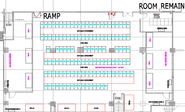
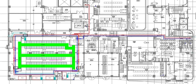
Site DC Layout
Based on the site situation and requirement, total 6 nos. of CRAC units (3 no.s per CRAC Room X 2 CRAC Rooms) to be proposed by fully utilized the cooling equipment space.
For the cooling configuration, 6 nos. of CRCAs (3 no.s per CRAC Room X 2 CRAC Rooms) will be in hot standby operation with spare 20% Cooling capacity as redundancy.
Data center design in total cold air flooding with hot aisle containment and return ducting concept where the room will be emersed by the cold air and hot air will be channeled by the containment and return ducting system back to the CRAC.
Mechanical and electrical installation is proper planned to achieve better space management and ease for the maintenance work.
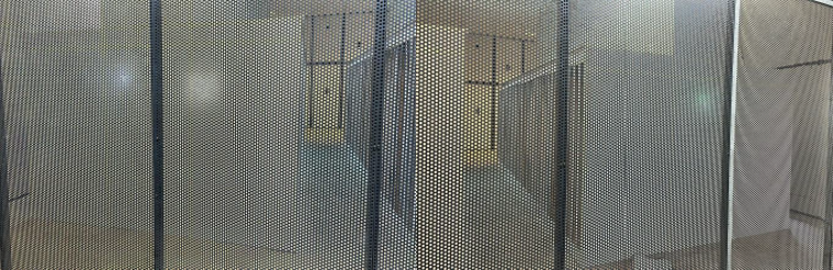
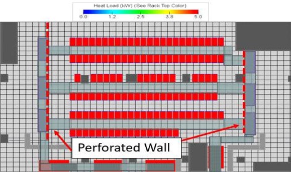
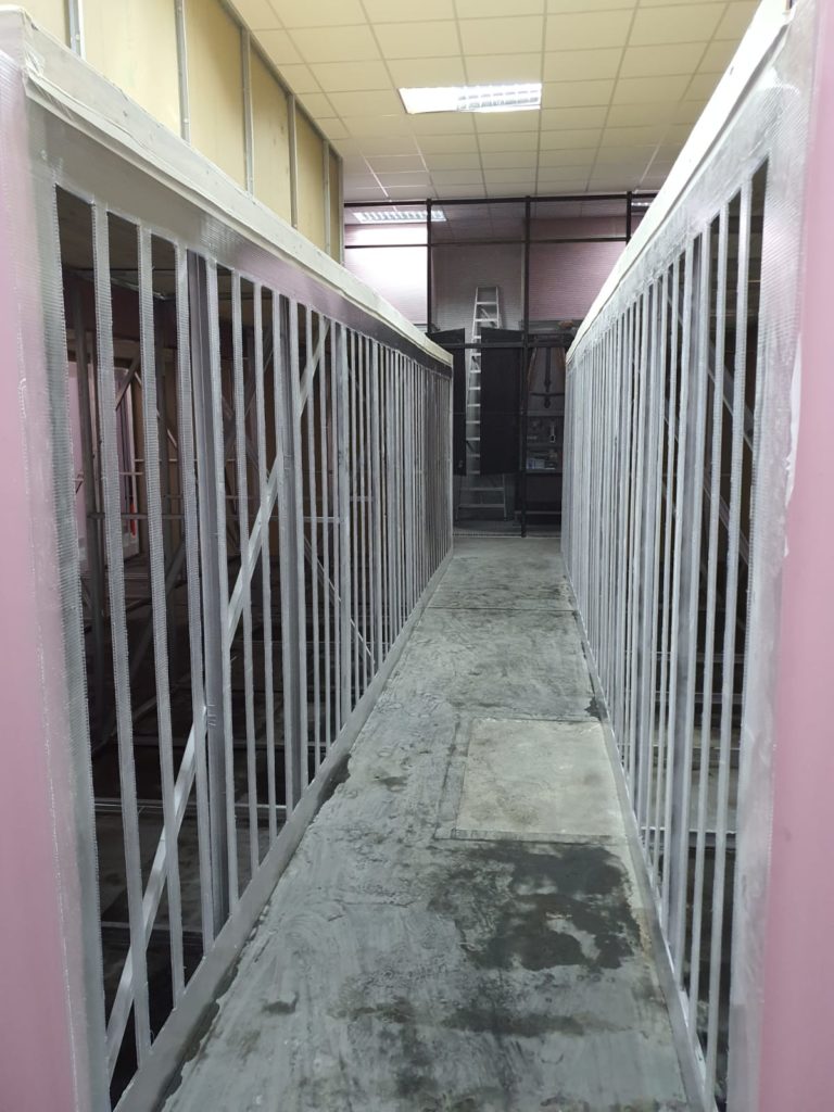
Perforated wall will be used to further improve the air distribution and cooling performance in the DC room.
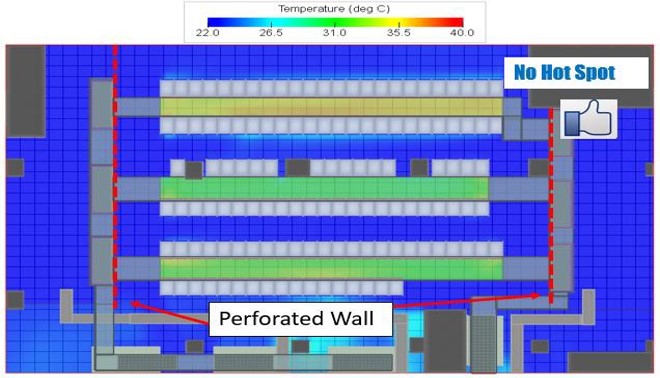
We are seeing inlet and outlet temperature of the server racks maintainns at normal control range based on ASHRAE requirement after initial CFD simulation based on the input data provided by client. The Hot Aisle Containment (HAC) approach encloses the hot aisle with return ducting above the aisle between adjoining racks and with doors at the end of the aisle. This allows the hot air from the IT racks to be contained and delivered to the CRAC air inlets. The HAC prevents cold air from mixing with warm air or being obstructed by surrounding equipment/sources before it reaches the servers. The Figure 4-6 is telling the same story and proves further on the HAC design concept.
DC Hall Temperature Distribution Analysis
Partnering Brands
AIRSYS
A trusted brand of cooling systems solutions for data centers, telecom facilities and medical systems throughout the world for over 20 years. The products have served a range of multinational customers and are widely recognized for its product quality and capability in providing precise temperature and humidity controls, outstanding reliability, energy efficiency and cost-effectiveness for round-the-clock operations.
Solutions:
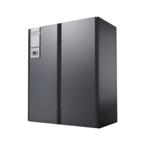
Computer Room Air-Conditioning (CRAC) Unit
Row Cooling System
Integrated Cabinet
Network Shelter Cooling
Chiller System
Ventilation & Heat Exchanger
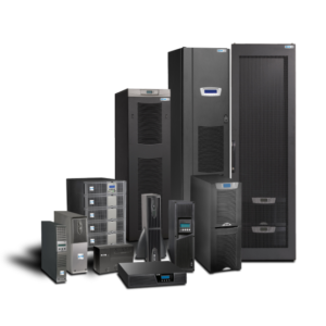
EATON Powerware
Offers a comprehensive array of power management solutions including uninterruptible power supplies, DC power solutions, surge protective devices, and power management software to support critical business needs.
Solutions
Uninterruptible Power Supply (UPS) System
DC Power Solution
Power Management Software
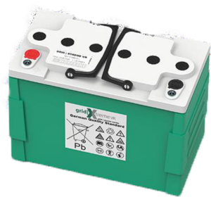
Hoppecke
They are known for manufacturing a wide range of industrial batteries and energy solutions for various applications, including forklifts, railway systems, renewable energy storage, and backup power systems. Hoppecke’s products include lead-acid batteries, lithium-ion batteries, and other energy storage solutions.
Solutions
Uninterruptible Power Supplies (UPS)
Telecommunication Battery
Lead-acid Battery
Pure Lead Battery
Engineering calculation
Integration & configuration
Product T&C
I. Level 0 Commissioning (Pre-commissioning Documentation) * documentation procedure and checklist on functional operability of equipment / component within the system in order to ensure the system is ready for start-up. * CxA shall review and approve the FWT procedure(s)
II. Level 1 Commissioning (Pre-commissioning Documentation) * must be submitted to the employer/design engineer and CxA at least sixty (60) working days in advance of the test for review and approval * a. Capacity of the equipment. * b. Safety features of the equipment. * c. Equipment safety/maintenance access. * d. A description of how conditions will be simulated in relation to the equipment operations. * e. Control and monitoring of equipment * f. Sequence of Operations (SOO)
III. Level 2 Commissioning– Pre-Start Up Documentation. * Pre-Start up Documentation for Manufacturer Equipment * Pre-energized equipment inspection
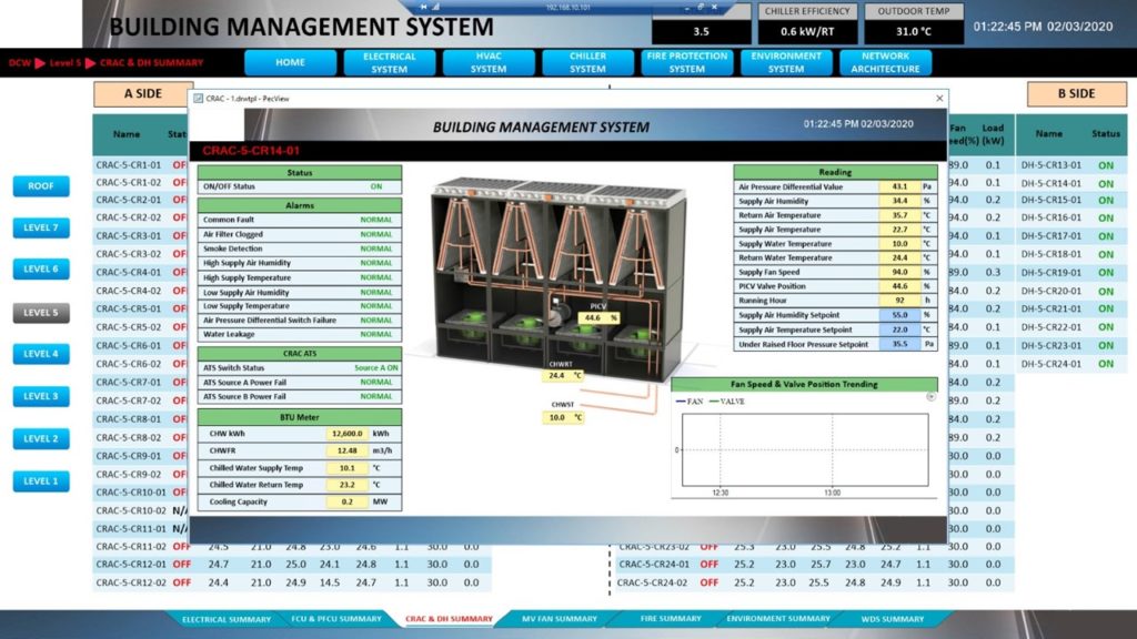
IV. Level 3 Commissioning – Equipment Start-Up and Pre-Functional Testing * prepare a detailed energization, start-up, and commissioning plan in consultation with the CxA, Contractor, and design consultant * The start-up activities of the equipment shall be performed by an authorized technician of the Sub-Contractor in accordance with the approved start-up plan. * Online Building Management System
V. Level 4 Commissioning – Functional Performance Testing (FPT) * From individual components, through complete systems the increasing interactions between components and other systems often does not produce the desired results. CxA team directs functional performance testing with assistance from an authorized manufacturer Sub-Contractor‘s technician and the installing contractor.
VI. Level 5 Commissioning – Integrated System Testing (IST) * In the IST, the facility is validated through a series of automated test procedures, performed without any human intervention, that are used to verify the system’s ability to respond to several anticipated situations. The test is intended to validate the performance of the systems under extreme operating conditions.